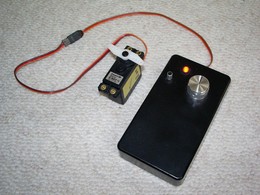
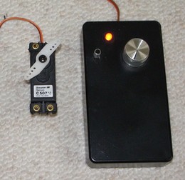
The final servo checker in action
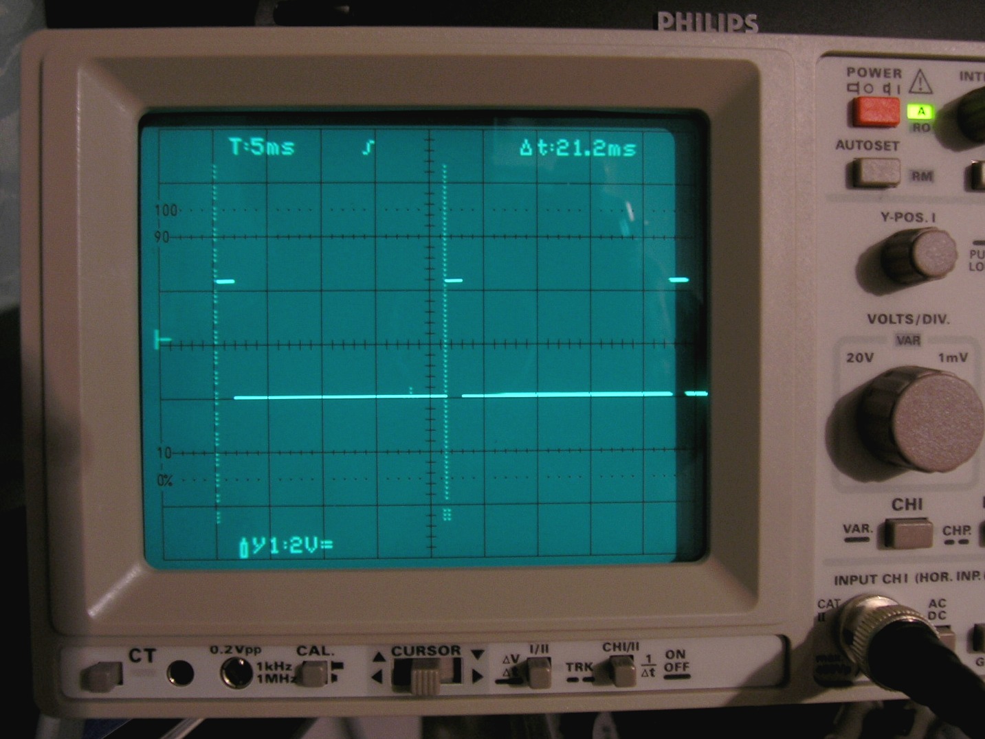
Pulse repetition period is 21.2 ms
(spacing of the two vertical markers)
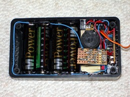
Fully packaged circuitry including 4 AA batteries
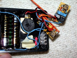
Quite dense packaging
Check your servos manually
This circuit shows a Servo-Checker for JR / Graupner /
Futaba-Components (positive impulse).
The output has an amplitude of approximately 5.0 Volt
(Graupner receiver output voltage).
|
The final servo checker in action |
Pulse repetition period is 21.2 ms |
|
|
Fully packaged circuitry including 4 AA batteries |
Quite dense packaging |
The first timer IC 555 creates a negative trigger signal
of approximately 45 Hz (a trigger impulse every 22 ms,
DO NOT exceed 50 Hz for proper servo function). The second
timer IC 555 modulates a positive square signal from
0.9 ms to 2.1 ms every 22 ms, a method commonly
known as pulse width modulation (PWM). The modulated pulse width
provides the full information for the exact servo position, and
allows a total swing of 140-160 degrees of the servo head
(see pictures below).
M is a trimmer to adjust the middle-position (the default pulse
width of 1.5 ms), the main input for the servo control is
the potentiometer P, which modulates the pulse width from
1.0 ms to 2.0 ms.
Note: Since the servo draws quite some instantaneous current (what might cause some power supply droops), ensure that there are sufficient capacitors to support the supply voltage (at least 100nF & 10uF). Otherwise the power supply droops slightly affect the timer circuitry: the pulse width may temporarily vary slightly, resulting in temporarily jerky servo movements.
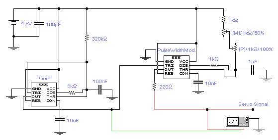
The green and red rods are corresponding to the signals on the
oscilloscope below.

A screen-shot of the signals in the simulation. The two markers
are 22.5 ms apart (T2-T1), the first pulse on the screen has
a width of approximately 1.0 ms, the second one a width of
approximately 2.0 ms.
 |
 |
 |
||
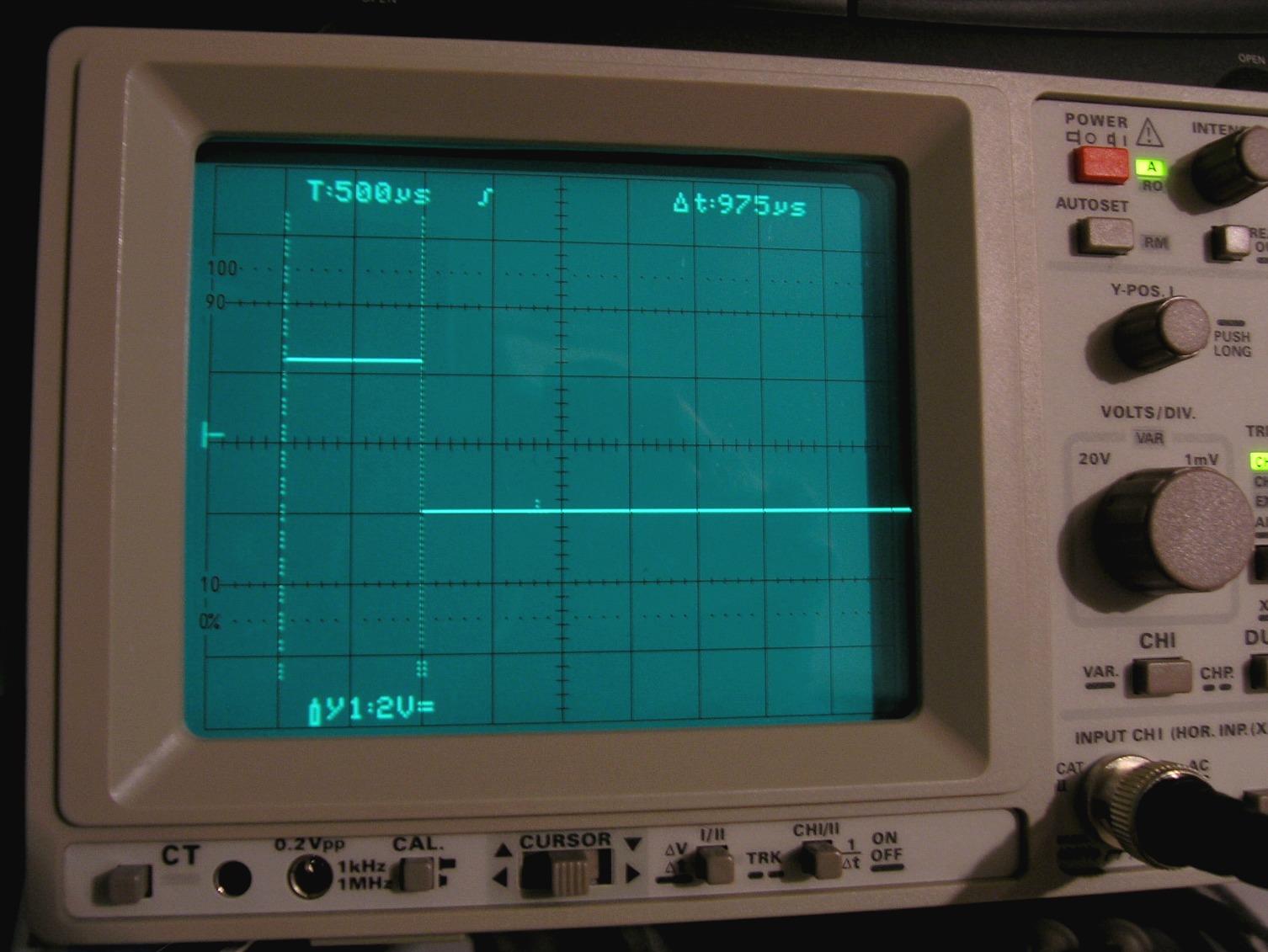
left servo end position: |
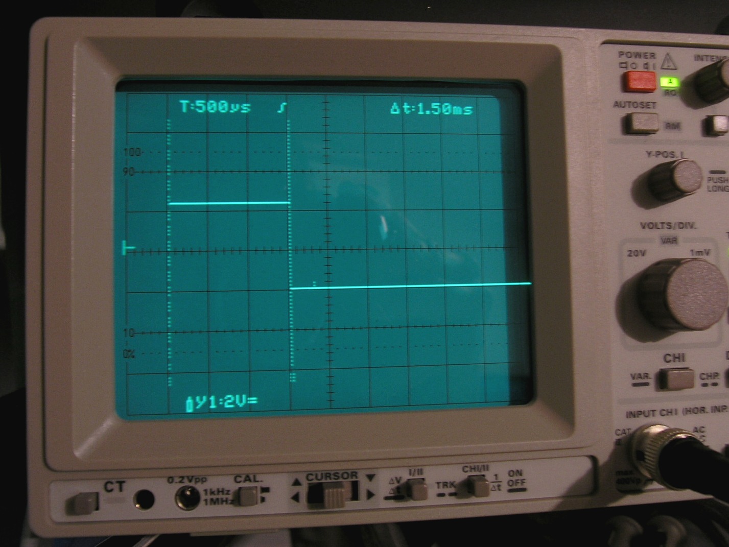
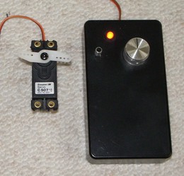
servo center position: |
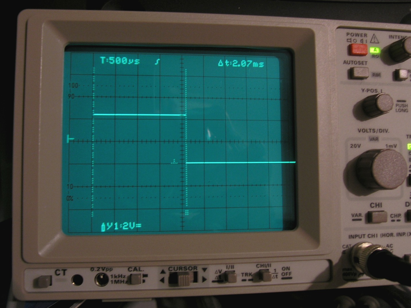
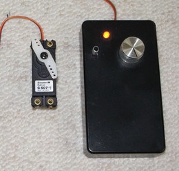
right servo end position: |
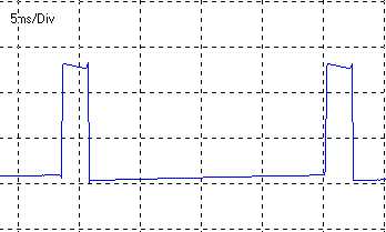
Qualitative signal acquisition using the freeware OSZI for
Windows 95. The pulse period is correct at about
22 ms.
At the time I have built this circuit, I did not have a native
hardware oscilloscope, so I used the soundcard of my PC.
Last updated: 06.08.2006