AT Keyboard Box V2.05
with Dot-Matrix LCD Display and numeric
Keypad for Microchip PIC16F77
Table of Contents [Toc]
Concept
How it works
Specifications
Parts order
information
Features
Limitations
Project Resources
Available PIC Assembler
Source Code
Schematics, Data Sheets,
Pinout
User-specific
Customization
Concept [Toc] [Top]
This implementation contains the complete fetch and decoding
of AT keyboard scan patterns as well as RS232 transmission and
reception of ASCII characters to and from the remote RS232
client. This microcontroller application also features an
interface to a dot matrix LCD display to visualize the the data
received from the RS232 client on the first line, and the
characters typed on the locally attached keyboard on the second
line. Further, the application has also a small numeric
foil-keypad and a piezo-beeper for acoustic feedback.
Dynamic configuration of RS232 baud
rate setting at start-up (user-customization with 1200 baud -
115200 baud), with 12 seconds inactivity time-out. In case the
time-out applies, the user-customization process terminates with
the current setting. Default setting after power-up is 9600
baud.
|
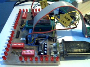
PIC16F77 development board
with
MAX232, serial port (and RS232 to USB1.1 connector) and dot
matrix LCD connection
|
|
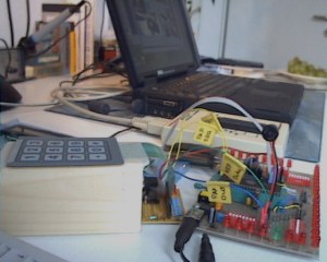
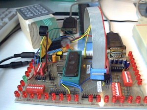
Workplace
with numeric foil-keypad,
interrupt generation circuit, PIC16C74A development board,
and laptop
|
|
|
|
|
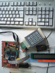
AT Keyboard Box V2.05 setup
with
numeric foil-keypad, dot matrix LCD display and AT
keyboard
|
|
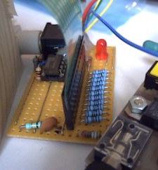
Interrupt generator
for numeric
foil-keypad: Whenever a key is hit, a key-specific analog
voltage is put on the first line to the A/D converter. At
the same time an interrupt is generated by this comparator
circuit and put on the second IRQ line.
|
|
|
|
|
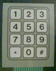
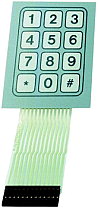
Numeric foil-keypad
Connection
topology: 1x12
|
|
Front view
Microchip PIC16C74A
microcontroller and piezo-beeper on the left side.
|
|
|
|
|
Screen shot of the HyperTerminal
Program
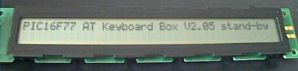
showing the start-up message of the
AT Keyboard Box V2.05
and some keyboard and keypad entries
|
How it works
[Toc] [Top]
Basically it works in the same way as the AT Keyboard Interface
V3.xx.
Here is only the description of the additional small numeric
foil-keypad. The numeric foil-keypad is equipped with a specific
resistor cascade to decode the values through direct 8 bit A/D
conversion using the PIC-internal A/D converter. The advantage
is a very low pin usage: Only two pins are necessary for
proper detection and decoding of all keypad entries. One pin
provides the analog value, the other pin serves for interrupt
generation whenever a key of the keypad is touched. The interrupt
is used to start the A/D conversion.
During the interrupt service routine, only a short busy wait
(analog settling time) and the A/D conversion - using the
internal RC oscillator - is carried out. Before leaving the ISR,
the 8 bit A/D result is stored in a specific register and a
dedicated flag is set.
Decoding of the A/D value is done during normal operation
(activated by the flag) using two look-up tables. The first
look-up table (LUT1) contains the expected 8 bit values of the
keypad to check for valid entries. A numeric window of ±3
allows for slight analog deviations during matching. The matching
algorithm just scans the entire LUT1 until the received keypad
A/D result matches a LUT1 entry. The amount of loops carried out
in LUT1 determines the position of the corresponding
symbol/character in LUT2. At the end, RS232 transmission and LCD
display update are carried out.
Dynamic configuration of RS232 baud rate setting at start-up
(user-customization with 1200 baud - 115200 baud). A
watchdog timer implemented using TMR1 checks for inactivity
during the customization process. After 12 seconds of
inactivity, the user-customization process terminates with the
current setting. At power-up, the default setting is 9600 baud,
which will be configured after the time-out - unless no
user-customization takes place.
This setup works also without attached foil-keypad, even if
the corresponding code is assembled and loaded into the
microcontroller.
|
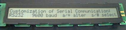
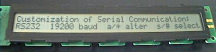
LCD display after power-up, ready for
customization of RS232
User customization is
done by pressing 'a' on the AT keyboard
or '*' on the numeric foil-keypad
|
|
|
|
|
LCD display after first alteration
(pressed button 'a' or '*' once)
|
|
|
|
|

LCD display after third alteration
(pressed again button 'a' or '*')
|
|
|
|
|
LCD display with completed user customization of
RS232
(pressed button 's' or '#' once)
|
|
|
|
|
LCD display showing locally entered data on second
line
(i.e. entered on local AT keyboard or foil-keypad)
|
|
|
|
|
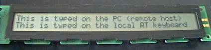
LCD display showing both remote and locally
entered data
(upper line was entered on remote host, lower line was
entered
on local AT keyboard or foil-keypad)
|
Specifications [Toc] [Top]
| Processor: |
PIC16F77 (PIC16C74A) |
| Clock Frequency: |
14.745600 MHz (HS mode) |
| Throughput: |
3.7 MIPS |
| RS232 Baud Rate: |
Customizable by user (BRGH =
0),
any setting from 1200 baud - 115200 baud |
| Serial Output: |
default setup: 9600 baud, 8 bit,
no parity, 1 stopbit |
| Keyboard Routine Features: |
Capability of bi-directional
communication between controller and keyboard |
| Numeric Keypad Features: |
Interrupt-based acquisition,
direct 8 bit A/D conversion |
| Acquisition Methodology: |
Preemptive, interrupt-based
keyboard scan pattern acquisition, decoding to ASCII
characters during normal operation mode activated by ready
flag (including LCD display and RS232 activities) |
| Code Size of entire
Program: |
1463 instruction words |
| Required Hardware: |
AT keyboard, PS/2 connector,
MAX232 level shifter, dedicated foil-keypad, LM393 comparator
circuity for interrupt generation, HD44780 compatible dot
matrix LCD (2x16, 2x20 or 2x40 characters) |
| Optional Hardware: |
Piezo beeper with decoupling
capacitor |
| Required Software: |
RS232 terminal software (or
Excel 97 RS232 Debug Interface) |
Note that every change in microprocessor clock frequency needs
a re-calibration and/or re-design of the analog foil-keypad
decoding circuitry.
Parts
order information [Toc] [Top]
 |
Numeric foil-keypad order information and technical
specifications:
www.conrad.de: FOLIENTASTATUR 1x12, Part-Nr.
709948-14 |
Features [Toc] [Top]
- Dynamic configuration of RS232 baud rate setting at
start-up.
- Bi-directional communication between microcontroller
application and remote RS232 client.
- Bi-directional communication between microcontroller and
keyboard.
- Bi-directional communication between microcontroller and
LCD display.
- Supports foil-keypad input through direct 8 bit A/D
conversion and look-up table.
- Piezo-beeper for acoustic feedback of keypad entries.
- Visualization of received and transmitted characters on
local LCD.
- Parametrizable LCD display width: constant 'LCDwidth'
- Support for all keyboard characters typed with shift button
active and inactive.
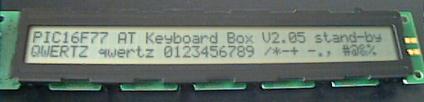
- English and modified Swiss-German 'codepages' available
(QWERTY and QWERTZ)
- Caps Lock implemented
- Num Lock always active
- Support of ASCII conversion from direct ALT-DEC entries,
e.g. ALT + 6 + 4 = @ (ALT + [1..3] numbers)
- Support of ASCII conversion from direct CTRL-HEX entries,
e.g. CTRL + 3 + F = ? (CTRL + [1..2] letters/numbers)
- ALT-DEC and CTRL-HEX features work for both, keypad and
keyboard numbers, as well as with upper and lower case letters
[a..f]
- Possibility to implement short-cuts or user defined
characters for 'Esc', 'Num Lock', 'Scroll Lock' and 'F1' -
'F12' keys.
Limitations
[Toc] [Top]
Basically the same limitations as for AT Keyboard Interface
V3.xx.
The analog foil-keypad decoding approach deserves dedicated
design and calibration: If a key on the keypad is hit, an
interrupt is generated to start the A/D conversion. The analog
value built by the keypad resistor cascade needs some
settling time until stable and reproduceable A/D values can be
read out by the PIC microprocessor (overshoots, undershoots).
This means that the PIC microprocessor clock frequency
(related to the A/D conversion speed), output drive strength of
the keypad resistor cascade and both debounce capacitors on IRQ
line and analog value pin affect the proper function of the
keypad circuit. Whenever the PIC clock frequency is changed,
(slight) adaptations on the analog circuitry may have to be
expected.
For calibration of the numeric foil-keypad, please refer to the
page 'Numeric
Foil-Keypad Calibration V0.04'.
Project Resources [Toc] [Top]
Available
Microchip PIC Assembler Source Code [Toc] [Top]
Schematics, Data
Sheets and Pinout [Toc] [Top]
AT Keyboard
Specification (PDF, 189 kB)
The schematics of the AT Keyboard Box using the PIC16F77:
You don't know how a dot matrix LCD is working? Have a look at
my data sheets page.
Download ASCII Character Map: ASCII-Map.pdf
You can get the description of the various keyboard connectors
<here>.
User-specific
Customization [Toc] [Top]
For a high level view, please refer to the section 'How it works' above.
Basically the same customization as for AT Keyboard Interface
V1.xx applies to this implementation.
If you apply changes to the existing code, you may need to
change the ORG directives in order to realign the assembler code
properly.
Last updated: 2004/12/26
[Toc] [Top]